Last updated: May 06, 2026
Beam Deflection Calculator

When a beam carries a load, it bends. That bending — measured as deflection — is one of the most important quantities in structural engineering. A beam that deflects too much cracks the ceiling below it, causes doors to jam, damages brittle floor finishes, and makes occupants feel an uncomfortable springiness underfoot. In extreme cases, excessive deflection is a precursor to structural failure. Designing against deflection is therefore not optional: every major structural code — AISC, Eurocode 3, AS 4100, BS 5950, and IS 800 — specifies deflection limits that must be satisfied alongside strength requirements.
The Beam Deflection Calculator at Intelligent Calculator handles the full range of structural beam analysis in one place. It computes maximum deflection, slope at the supports, support reactions, and bending moment diagrams for simply supported beams, cantilevers, fixed-fixed beams, and propped cantilevers under point loads, uniformly distributed loads, and combined loading. It calculates section properties for standard cross-sections, optimises the required moment of inertia for a given deflection limit, and checks compliance against five international structural codes simultaneously.
This guide explains every concept behind those calculations, walks through the governing formulas for each beam configuration, provides worked examples, and gives you the code deflection limits you need to design beams that are not just strong enough but stiff enough.
What Is Beam Deflection?
Beam deflection is the transverse displacement of a beam from its original unloaded position when it is subjected to an applied load. When a simply supported beam carries a load at mid-span, its centre drops downward relative to the supports. The maximum value of that downward displacement — measured at the point of greatest movement — is the maximum deflection, commonly denoted by the Greek letter delta (δ).
Deflection is a serviceability concern rather than a strength concern. A beam may be perfectly capable of carrying its load without breaking while still deflecting so much that it fails the serviceability requirements of the applicable code. This is why structural design involves two separate checks: an ultimate limit state check to ensure the beam does not fail under factored loads, and a serviceability limit state check to ensure deflection under unfactored or service loads stays within the code-specified limit.
The amount a beam deflects depends on four variables: the applied load and its distribution, the span length, the material’s modulus of elasticity, and the cross-section’s second moment of area. Understanding how each variable influences deflection — and knowing which lever to pull to reduce it — is the practical knowledge the calculator is built to support.
Key Terms in Beam Deflection Analysis
Flexural Rigidity (EI)
Flexural rigidity is the product of the modulus of elasticity (E) and the second moment of area (I) of the beam cross-section. It is the single most important property governing how much a beam deflects under a given load. A high EI value means a stiff beam that deflects little. Flexural rigidity appears in the denominator of every deflection formula — doubling E or doubling I halves the deflection. Steel has a modulus of elasticity of approximately 200 GPa. Timber ranges from 7 to 14 GPa depending on species and grade. Concrete is typically 25–35 GPa but its effective stiffness is reduced by cracking.
Second Moment of Area (I)
The second moment of area, also called the moment of inertia, measures how a cross-section’s area is distributed about its neutral axis. Cross-sections with more material located farther from the neutral axis have higher I values and are more resistant to bending. This is why I-beams and H-sections are so efficient structurally: the flanges carry most of the bending stress while the web mainly resists shear. For a solid rectangular section of width b and depth h, the second moment of area about the horizontal axis is bh³/12. Doubling the depth increases I by a factor of eight — making depth the most powerful variable for reducing deflection in a standard beam.
Span Length (L)
Span length has the most dramatic effect on deflection of all the variables. In simply supported and cantilever beam formulas, deflection is proportional to L³ or L⁴ depending on the load type. Doubling the span of a simply supported beam under a point load increases deflection by a factor of eight. This is why spanning greater distances without intermediate supports demands progressively larger, deeper, or higher-strength beam sections — not just proportionally larger.
Boundary Conditions
The way a beam is supported at its ends fundamentally changes how it deflects. A simply supported beam is free to rotate at both ends but cannot translate vertically. A cantilever is fully fixed at one end and completely free at the other. A fixed-fixed beam is restrained from both rotation and translation at both ends. A propped cantilever is fixed at one end and simply supported at the other. Each configuration produces different deflection formulas, different maximum deflection locations, and different reactions. Selecting the wrong boundary condition for a beam’s actual support conditions produces incorrect results.
Deflection Limit Ratio (L/n)
Code deflection limits are expressed as a fraction of the span. A limit of L/360 means the maximum deflection must not exceed the span divided by 360. For a 6-metre span, L/360 equals 16.7 mm. The denominator n gets larger as requirements become stricter — L/500 is a tighter limit than L/250. Different applications have different limit ratios: floors supporting brittle finishes are typically limited to L/360, while general roof structures may only need to satisfy L/200.
Beam Deflection Formulas by Configuration

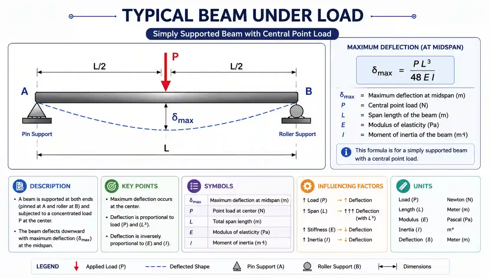
Simply Supported Beam — Central Point Load
A simply supported beam with a single concentrated load P applied at mid-span is the most commonly encountered configuration in practice and the standard reference case in structural design.
δ_max = PL³ / (48EI)
The maximum deflection occurs at mid-span. The slope at each support is PL²/(16EI). The reactions at each support are equal at P/2. This formula is the baseline from which many practical design checks begin.
Simply Supported Beam — Uniformly Distributed Load (UDL)
A uniformly distributed load of intensity w (force per unit length) spread over the full span represents floor loading, self-weight, and many service loads in practice. The total load W equals w × L.
δ_max = 5wL⁴ / (384EI)
Maximum deflection again occurs at mid-span. The coefficient 5/384 is approximately 0.0130. The reactions at each support are wL/2. The UDL formula produces 60% of the deflection of an equivalent total load applied as a central point load — distributed loading is more efficient than concentrated loading.
Cantilever Beam — End Point Load
A cantilever is fixed at one end and free at the other. It is far less stiff than a simply supported beam of the same length because the fixed support must resist the full bending moment, and there is no load-sharing between two reactions.
δ_max = PL³ / (3EI)
The maximum deflection occurs at the free end. The fixed support carries a reaction equal to P and a moment equal to PL. Comparing this formula with the simply supported central load case reveals that the cantilever deflects 16 times more than a simply supported beam of the same span, load, and section. This is why cantilever spans must be limited or substantially deeper sections used.
Cantilever Beam — Uniformly Distributed Load
A cantilever carrying a UDL along its full length — such as a balcony with a uniform floor load — deflects according to the following formula, where w is load per unit length.
δ_max = wL⁴ / (8EI)
The coefficient 1/8 equals 0.125, compared to 5/384 ≈ 0.013 for the simply supported UDL case. The cantilever deflects roughly nine times more than a simply supported beam of equal span and loading under a UDL — confirming that cantilever spans must be designed conservatively.
Fixed-Fixed Beam — Central Point Load
A beam fixed against rotation at both ends develops hogging moments at each support in addition to the sagging moment at mid-span. These end moments reduce mid-span deflection dramatically compared to the simply supported case.
δ_max = PL³ / (192EI)
The coefficient 1/192 compares with 1/48 for the simply supported case — a fixed-fixed beam is four times stiffer than a simply supported beam under a central point load. Fixed-end moments at each support equal PL/8, and the mid-span moment is also PL/8, giving a uniform bending moment envelope that uses the section efficiently.
Fixed-Fixed Beam — Uniformly Distributed Load
δ_max = wL⁴ / (384EI)
The coefficient 1/384 compares to 5/384 for the simply supported UDL — a fixed-fixed beam under a UDL is five times stiffer than a simply supported beam. Fixed-end moments at each support equal wL²/12, and mid-span moment equals wL²/24.
Deflection Formula Summary by Configuration
| Beam Type | Load Type | Max Deflection Formula | Location of δ_max | Relative Stiffness |
| Simply supported | Central point load P | PL³ / 48EI | Mid-span | Baseline (1×) |
| Simply supported | Full UDL (w per unit length) | 5wL⁴ / 384EI | Mid-span | 0.8× vs equiv. point load |
| Simply supported | Eccentric point load Pa b | Pa²b² / 3EIL (at load) | Under load | Varies with position |
| Cantilever | End point load P | PL³ / 3EI | Free end | 16× less stiff than SS |
| Cantilever | Full UDL (w per unit length) | wL⁴ / 8EI | Free end | ~9× less stiff than SS |
| Fixed-fixed | Central point load P | PL³ / 192EI | Mid-span | 4× stiffer than SS |
| Fixed-fixed | Full UDL (w per unit length) | wL⁴ / 384EI | Mid-span | 5× stiffer than SS |
| Propped cantilever | Central point load P | 0.00932 PL³/EI | ~0.42L from fixed end | ~2.5× stiffer than SS |
| Propped cantilever | Full UDL (w per unit length) | wL⁴ / 185EI | ~0.42L from fixed end | ~2.4× stiffer than SS |
How to Use the Beam Deflection Calculator — Step by Step
Step 1: Select Your Beam Configuration
Choose the boundary condition that matches your physical beam. A floor joist sitting on two walls is simply supported. A balcony slab projecting from a wall is a cantilever. A beam bolted rigidly into reinforced concrete columns at both ends approximates a fixed-fixed beam. Selecting the wrong configuration is the most consequential input error — it changes both the deflection magnitude and the shape of the bending moment diagram.
Step 2: Enter Span Length
Enter the clear span between supports in meters. For simply supported beams, this is the distance between the centrelines of the two supports. For cantilevers, it is the distance from the fixed support to the free end. Accuracy matters: deflection is proportional to L³ or L⁴, so a 5% error in span produces a 15–20% error in the calculated deflection.
Step 3: Define the Load
Select whether the load is a concentrated point load (in kilonewtons), a uniformly distributed load (in kilonewtons per metre), or a combination of both. Enter the load magnitude. For a point load on a simply supported beam, also specify the load position as a distance from the left support. The calculator handles eccentric point loads using the full two-parameter formula, not the simpler mid-span approximation.
Step 4: Enter Section and Material Properties
Enter the modulus of elasticity E in gigapascals (GPa) and the second moment of area I in centimetres to the fourth power (cm⁴). Standard values are 200 GPa for structural steel, 70 GPa for aluminium, and 10–12 GPa for structural timber. The I value is found in section property tables for standard steel sections (UB, UC, RHS, CHS) or calculated from the cross-section geometry using the Section Properties card of the calculator, which covers rectangular, circular, I-section, T-section, and hollow box sections.
Step 5: Review Results and Check Compliance
The calculator returns maximum deflection in millimetres, the slope at each support in radians, support reactions in kilonewtons, the fixed-end moments where applicable, and the L/delta ratio expressing deflection as a fraction of span. The Code Compliance card then checks this L/delta ratio against the deflection limits of AISC, Eurocode 3, AS 4100, BS 5950, and IS 800, displaying a pass or fail result for each standard alongside the application-specific limit for the selected use case.
Worked Example: Office Floor Beam
The Scenario
An office floor beam spans 7.5 metres between columns. It carries a uniformly distributed load of 18 kN/m from the floor slab, services, and imposed office load. The beam is a simply supported 406×178×74 UB (Universal Beam) in Grade S275 steel. The designer needs to verify that the beam satisfies the L/360 serviceability deflection limit specified for a floor supporting brittle plaster ceilings.
Section Properties for 406×178×74 UB
| Property | Value | Notes |
| Depth (h) | 412.8 mm | Overall section depth |
| Flange width (b) | 179.5 mm | Flange width |
| Second moment of area (I_xx) | 27,290 cm⁴ | About major (strong) axis |
| Modulus of elasticity (E) | 200 GPa | Structural steel (all grades) |
| Flexural rigidity (EI) | 200,000 × 27,290 × 10⁻⁸ m⁴ | Units: kNm² |
| EI in consistent units | 54,580 kNm² | E in kN/m², I in m⁴ |
Deflection Calculation
δ_max = 5wL⁴ / 384EI
w = 18 kN/m | L = 7.5 m | EI = 54,580 kNm²
δ_max = (5 × 18 × 7.5⁴) / (384 × 54,580)
δ_max = (5 × 18 × 3,164.06) / (20,958,720)
δ_max = 284,765 / 20,958,720 = 0.01359 m = 13.6 mm
Code Compliance Check
| Check | Calculation | Result | Limit | Status |
| Allowable deflection (L/360) | 7,500 mm ÷ 360 | 20.8 mm | 20.8 mm max | — |
| Actual deflection | Calculated above | 13.6 mm | ≤ 20.8 mm | PASS |
| L/delta ratio | 7,500 ÷ 13.6 | L/551 | ≥ L/360 required | PASS |
| AISC L/360 live load limit | 20.8 mm allowed | 13.6 mm actual | PASS | PASS |
| Eurocode L/350 limit | 7,500 ÷ 350 = 21.4 mm | 13.6 mm actual | PASS | PASS |
| BS 5950 L/360 limit | 7,500 ÷ 360 = 20.8 mm | 13.6 mm actual | PASS | PASS |
The 406×178×74 UB satisfies the L/360 deflection limit with a margin of 35%. The designer may choose to use this section or investigate whether a lighter section — with a lower I value — still passes. The Section Optimiser card of the calculator can determine the minimum I required for any deflection limit, allowing efficient section selection without iterating through tables manually.
Planning a masonry project alongside structural beam analysis? Use our Brick Calculator to estimate the number of bricks and materials needed for your construction project. It helps save time, reduce waste, and improve planning accuracy.
International Code Deflection Limits
Every major structural design code specifies deflection limits for beams and members in terms of their span. These limits are serviceability requirements, applied to unfactored service loads rather than the factored loads used for strength design. The following table summarises the limits from the five codes covered by the calculator.
| Application | AISC 360 | Eurocode 3 (EN 1993) | AS 4100 | BS 5950-1 | IS 800 |
| Floor — general | L/240 total | L/250 total | L/250 total | L/200 total | L/325 total |
| Floor — brittle finish | L/360 live | L/350 live | L/300 live | L/360 live | L/300 live |
| Roof — general | L/240 total | L/200 total | L/200 total | L/200 total | L/240 total |
| Roof — drainage sensitive | L/300 total | L/250 total | L/250 total | L/250 total | L/325 total |
| Cantilever | L/180 total | L/250 total | L/250 total | L/180 total | L/300 total |
| Gantry / crane girder | L/600 live | L/600 live | L/600 live | L/600 live | L/750 live |
| Facade / cladding rail | L/200 | L/200 | L/250 | L/200 | L/300 |
| Sensitive finishes | L/480+ | L/500 | L/500 | L/360+ | L/500 |
These limits are minimum requirements. Project specifications, client briefs, or the sensitivity of particular finishes or equipment may impose stricter limits. Semiconductor fabrication floors, for example, sometimes specify L/1000 or tighter to prevent vibration interfering with manufacturing processes. The calculator accepts any user-defined deflection limit ratio in addition to the standard code values.
Section Properties and Their Effect on Deflection
The second moment of area I is the cross-section property that directly controls beam stiffness. Selecting a cross-section with adequate I for a given span, load, and deflection limit is the core structural design task that the calculator’s Section Optimiser automates.
| Cross-Section | I Formula | Relative I (same height h, width b) | Best Application |
| Solid rectangle | bh³ / 12 | Baseline (1.0×) | Timber, RHS, general purpose |
| Solid circle (diameter d) | πd⁴ / 64 | 0.785× (d=h) | Circular sections, columns |
| Hollow rectangle (RHS) | b_out·h_out³/12 − b_in·h_in³/12 | Higher than solid for same mass | Steel RHS, efficient spans |
| I-Section (UB/UC) | b·h³/12 − 2×(b−t_w)·h_w³/12 | 3–5× solid rect of same height | Steel floor and roof beams |
| T-Section | Centroid + parallel axis theorem | 2–3× solid rect | Concrete flanged beams |
| Hollow circle (CHS) | π(d_out⁴ − d_in⁴) / 64 | High per unit weight | Columns, trusses, masts |
The I-section’s dominance in steel construction is directly attributable to its second moment of area. By concentrating material in the flanges — far from the neutral axis — an I-section achieves a dramatically higher I value than a solid rectangle of the same cross-sectional area. This efficiency translates directly into reduced deflection and reduced material cost. The Section Properties card of the calculator computes I for each of these cross-section types from the entered dimensions, and the Section Optimiser then determines the minimum I required for the loading and deflection limit specified.
Material Modulus of Elasticity Reference
| Material | E (GPa) | Typical Beam Application | Notes |
| Structural steel (all grades) | 200 | Universal beams, columns, trusses | E independent of grade (S235–S460) |
| Stainless steel | 193–200 | Architectural, corrosive environments | Slightly lower than carbon steel |
| Aluminium alloy (6061-T6) | 69 | Lightweight structures, aerospace | Deflects ~2.9× more than steel |
| Concrete (normal weight) | 25–35 | RC slabs, beams — uncracked | Cracking reduces effective E significantly |
| Timber — Douglas Fir (C24) | 11 | Joists, rafters, structural timber | EN 338 characteristic value |
| Timber — LVL / Glulam | 12–14 | Long-span timber beams | More consistent than sawn timber |
| Glass fibre (GFRP) | 20–45 | Specialist lightweight bridges | Orthotropic; check manufacturer data |
| Carbon fibre (CFRP) | 70–200 | High-performance retrofitting | Highly variable by fibre volume |
Engineers working with fluid systems and industrial piping can also use our Pipe Volume Calculator to quickly calculate the volume of liquid inside a pipe based on diameter and length. It’s perfect for plumbing, engineering, and industrial applications with precise results.
How to Reduce Beam Deflection — Design Strategies
Increase Beam Depth
Depth is the most powerful variable available to the designer. Because I is proportional to h³ for a rectangular section, doubling the depth increases stiffness eightfold. Even increasing depth by 20% — for example, moving from a 356 UB to a 406 UB — increases I by roughly 75%, reducing deflection by about 43%. Increasing depth is always the first strategy to investigate when a deflection check fails.
Reduce the Span
Adding an intermediate support reduces the effective span of the beam. Because deflection varies with L³ or L⁴, halving the span reduces deflection by a factor of 8 to 16. Introducing a column or wall support mid-span converts a single-span simply supported beam into two continuous spans, which also reduces mid-span moments and therefore further reduces deflection beyond the simple span-reduction effect. For projects involving accessibility slopes, inclines, and structural rise calculations, use our Ramp Calculator to calculate slope, incline, length, and rise measurements with accurate results. It’s ideal for wheelchair ramps, construction projects, and accessibility planning.
Increase the Modulus of Elasticity
Switching from timber to steel increases E by a factor of roughly 18, reducing deflection by the same factor for an equivalent section. Switching from aluminium to steel nearly triples stiffness. Material selection is typically constrained by application, cost, and aesthetics, but in cases where excessive deflection cannot be resolved by geometry alone, specifying a stiffer material is a valid engineering solution.
Apply Precamber
Precamber is an intentional upward bow built into a beam during fabrication. When the dead load is applied after installation, the beam deflects downward and the precamber disappears, leaving the beam approximately level. Precamber addresses the permanent dead load component of deflection only — it does nothing to reduce live load deflection that must still satisfy the code limit. It is commonly applied to steel beams spanning more than 12 metres in building construction.
Use a Stiffer Boundary Condition
Where connections can be made fully rigid, converting a simply supported beam to a fixed-fixed configuration reduces deflection by a factor of four for a central point load or five for a UDL. Even partial fixity — moment-resisting connections that are not fully rigid — significantly reduces deflection compared to pinned connections. The cost is that the connection detail becomes more complex and the fixed-end moments must be designed for in the column or supporting structure.
Common Beam Deflection Calculation Mistakes
Mistake 1: Applying the Wrong Boundary Condition
Treating a beam as simply supported when it is partially or fully fixed underestimates stiffness and produces a conservative (over-designed) result. Treating a fixed beam as simply supported is the more dangerous error: it overestimates stiffness and produces a deflection prediction that is too small, potentially leading to a section that deflects more than predicted in service. Always model boundary conditions to match the actual connection behaviour.
Mistake 2: Using Factored Loads for Serviceability Checks
Code deflection limits apply to unfactored service loads, not the factored loads used in strength design. Using 1.4 or 1.5 times the service load in a deflection calculation produces a deflection value roughly 40–50% too large, potentially causing a section to be unnecessarily upsized. All deflection checks must use characteristic (unfactored) load values.
Mistake 3: Using the Wrong I Value (Wrong Axis)
Standard section property tables list I values about both the major axis (I_xx) and the minor axis (I_yy). For a UB or UC section, I_xx can be 10–50 times larger than I_yy. Using I_yy instead of I_xx in a calculation for a beam bending about its major axis produces a deflection result that is catastrophically wrong. Always confirm which axis the beam bends about and use the corresponding I value.
Mistake 4: Neglecting Long-Term Deflection in Timber
Timber beams creep under sustained load — they continue to deflect slowly over time beyond their initial elastic deflection. Eurocode 5 and other timber codes apply a creep modification factor (k_def) to account for this. A timber beam that satisfies the L/250 limit under initial loading may exceed it after several years of sustained load if creep is not accounted for. The effective E value used in long-term timber calculations is lower than the short-term value by the creep factor, which ranges from 0.6 to 2.0 depending on service class and load duration.
Mistake 5: Ignoring Shear Deformation in Deep Beams
Standard beam deflection formulas based on Euler-Bernoulli beam theory account only for bending deformation. For slender beams with a span-to-depth ratio greater than about 10, this is accurate. For deep beams with a span-to-depth ratio less than 5, shear deformation contributes significantly to total deflection and must be included using Timoshenko beam theory. The calculator uses the standard Euler-Bernoulli formulas, which are appropriate for the vast majority of practical building beam applications.
Frequently Asked Questions
What is L/360 deflection limit and when does it apply?
L/360 is a serviceability deflection limit where the maximum allowable deflection equals the beam span divided by 360. For a 6-metre beam, L/360 equals 16.7 mm. This limit is commonly applied to floor beams supporting brittle finishes — plaster ceilings, ceramic tiles, or similar materials that crack when they experience movement. It is the live load deflection limit in AISC 360 for this application. Beams supporting more flexible finishes or roofs without drainage sensitivity are typically designed to the less strict L/240 or L/200 limit.
Why does doubling the span increase deflection so much?
Deflection is proportional to span raised to the third or fourth power depending on the load type. For a simply supported beam under a UDL, the formula is 5wL⁴/384EI — span appears to the fourth power. Doubling L while keeping all other variables constant increases L⁴ by a factor of 2⁴ = 16. This is why achieving the same deflection limit over a longer span requires a dramatically stiffer section. Tripling the span would increase deflection by a factor of 81, requiring an 81-fold increase in EI to maintain the same deflection.
What is the difference between deflection and settlement?
Beam deflection is the elastic bending of the beam itself under load — it occurs immediately when load is applied and is recovered when load is removed. Settlement is the movement of the foundations supporting the beam, caused by consolidation or compression of the soil beneath. Settlement is permanent and continues over months or years. Both deflection and settlement affect the level of a floor or the alignment of a structure, but they have completely different causes, timescales, and design solutions. Beam deflection calculations address only the beam’s own bending behaviour, not foundation movement.
Can I use this calculator for reinforced concrete beams?
The calculator can be used for reinforced concrete beams with care. The key complication is that concrete cracks in the tension zone when bending stress exceeds its tensile capacity, which significantly reduces the effective second moment of area below the uncracked gross section value. Eurocode 2 and ACI 318 define methods for calculating the effective (cracked) I value as a weighted average between the fully cracked and uncracked values. Enter the effective I_eff rather than the gross I_gross, and use the short-term elastic modulus for the load case being checked. Long-term concrete deflections also include a creep multiplier that increases deflections by a factor of 2 to 3 over time.
How do I find the second moment of area for a steel section?
For standard steel sections, I values are published in section property tables produced by steel manufacturers and structural engineering handbooks. In the UK, the SCI Steel Construction Institute publishes the Blue Book (P363) with comprehensive section property tables for all standard UB, UC, RHS, CHS, and angle sections. AISC publishes equivalent tables in its Steel Construction Manual. The calculator’s Section Properties card can compute I directly from entered dimensions for rectangular, circular, I-section, T-section, and hollow box geometries, covering the common non-standard or compound sections.
What deflection limit applies to a cantilever balcony?
Cantilever members are often subject to stricter deflection limits than simply supported spans because the visual impact of a sagging cantilever tip is more noticeable and can cause concern to occupants even if structurally harmless. Common limits for cantilevers in building codes range from L/180 (AISC, BS 5950) to L/250 (Eurocode 3, AS 4100). For cantilevers supporting brittle finishes, L/360 based on the live load component is often specified. Because cantilever deflection under a UDL is proportional to L⁴/8EI compared to L⁴/384 for a comparable simply supported span, achievable cantilever spans with standard sections are significantly shorter than simply supported spans for the same deflection limit.
Final Thoughts
Beam deflection sits at the heart of structural serviceability design. Getting the calculation right — using the correct formula for the boundary condition, the correct I value for the bending axis, unfactored loads, and the applicable code limit for the end use — is what separates a beam that performs well in service from one that cracks finishes, jams doors, or fails a code compliance check. The Beam Deflection Calculator at IntelCalculator puts every formula, every code limit, and every section property calculation in one place. Enter your beam, your load, and your section — and get results you can take directly into your design documentation.
Use our free Construction Calculator suite to handle ramp geometry, area measurements, material estimation, and structural calculations. Try our Square Meter Calculator to quickly calculate area measurements in square meters with accurate results. It’s useful for flooring, construction, painting, and property measurements.
| Beam Type | Formula | Deflection | Status (L/250) |
|---|
| Application | Limit | Max delta (mm) | I required (cm⁴) |
|---|